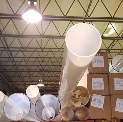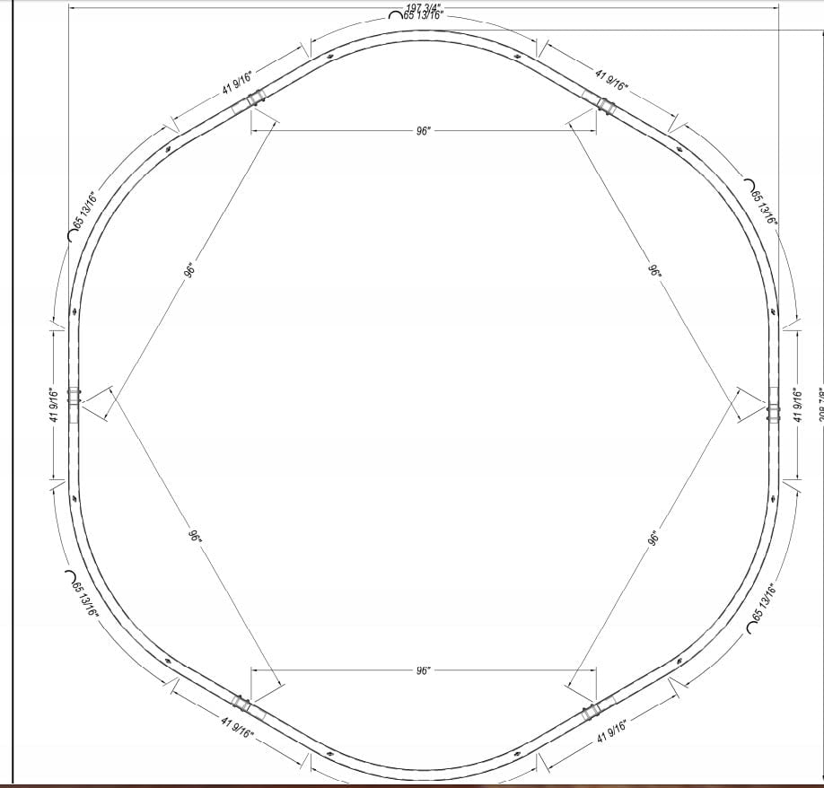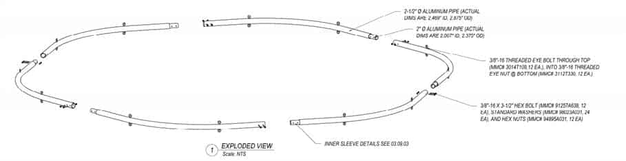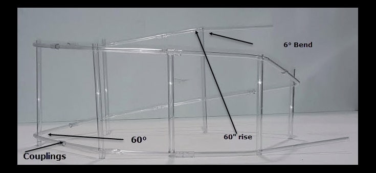
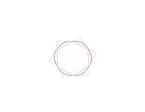
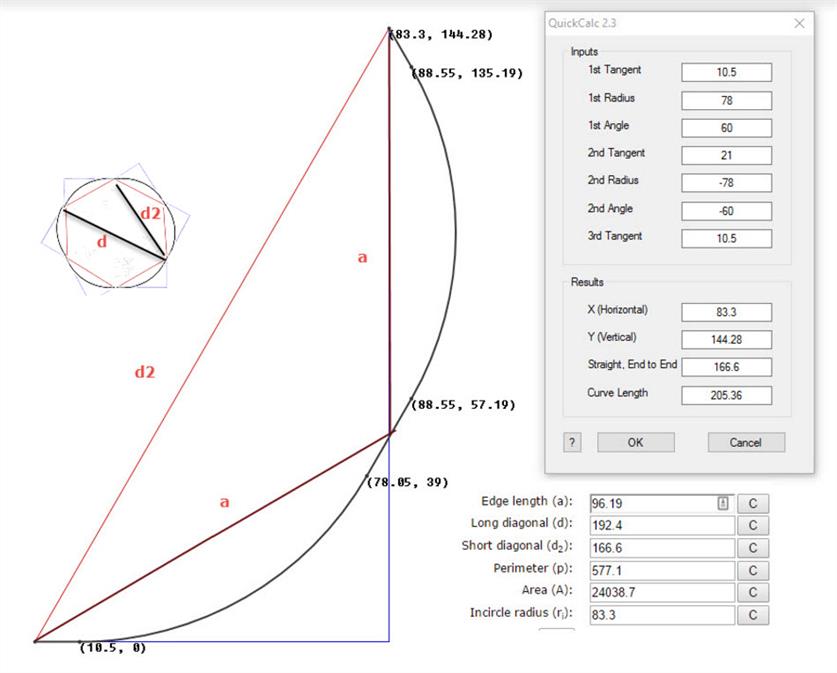
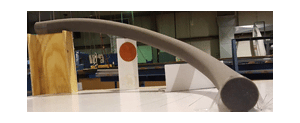
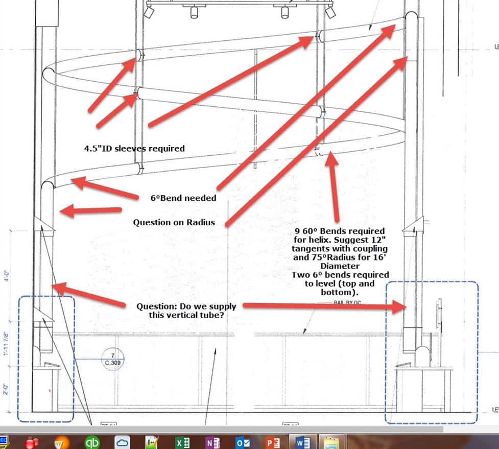
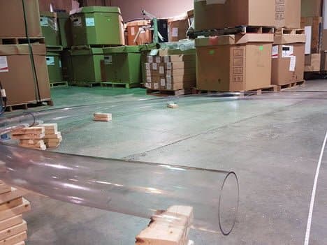
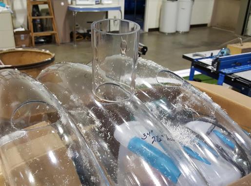
We are privileged to participate in a helical bend for a children’s museum in Baton Rouge. More later as this develops. The helix (hexagonal) has a 96″ radius and composed of (CAB) cellulose acetate tubing (4.125″ID).
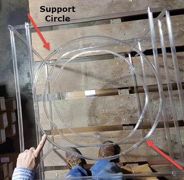
Model 1 and support circle.
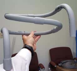
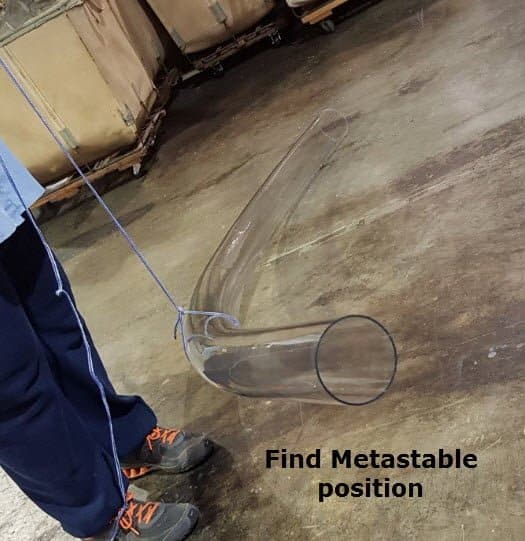
Ideas on suspension. There is a position along the bend where you could suspend it and have very little tendency for it to rotate or sag. We need to find this point on the bends. The key is to find this point on a 60° bend.Take the bend and with one end on the ground pick up the other end it will tend to rotate so that the bend hangs down. Next with one end on the ground,lift it just above the middle, the top end will try to point down. It will swivel in the opposite direction to the first experiment. There is a position between half way and the end where it has no real tendency to go either way, but will still swivel if you let it as that is a metastable state. But restraining it from twisting requires the merest touch. My guess is that position is between one quarter to one third of the way from the top end. That is the ideal suspension point.
The reaction on the couplings is at a minimum and it will be the easiest to assemble as it will twist whichever way you want to align the tangents really easily. It is probable that the supports from the roof will be rotated in plan view about15-20° from what the drawings show.
The effect of the shuttle or carrier. Newton’s laws — or action and opposite reaction. It won’t change speeds on the bends unless the friction is really high. The air velocity is going to be the main thing that governs the speed and so changing the tangents does not seem to be needed.
A simple wire from the suspension to some point on the ceiling inside of the helix would resist swinging movement. The suspension would then be a triangle of a vertical strut and an angled wire. Angled in towards the center as the centripetal force would be directed out from the center. If the helix did sway we may have to allow the horizontal legs to have a bit of flexibility. Maybe just pin the coupler with a little slack rather than glue it tight.
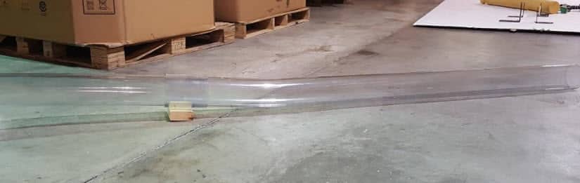
Banking Carrier on a straight section.
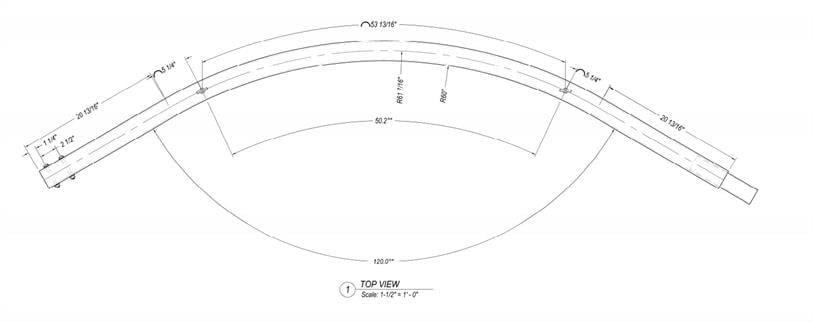
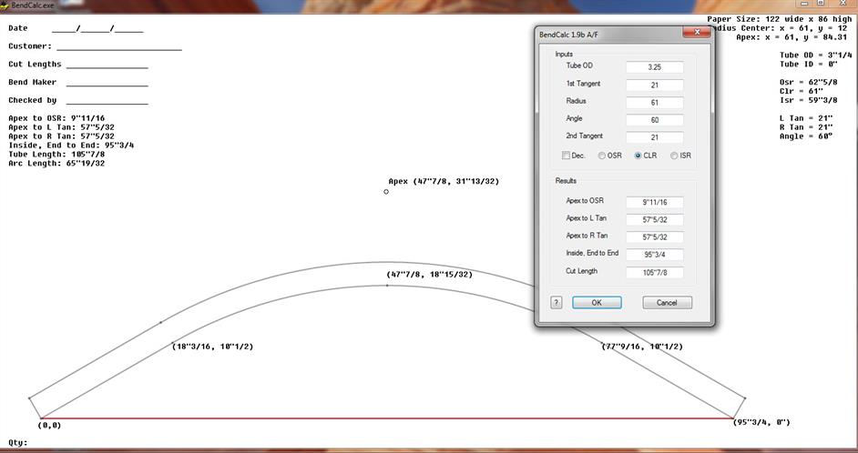
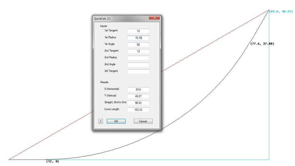
Suggestion for 12″ tangents on 60 Deg
Below is the size bend that we want to propose. It has 12″ of tangents which gives us ample wiggle room to install, but the majority of the helix will be curved. We believe that this will make travel smoother than the tight radius bends with longer tangents.
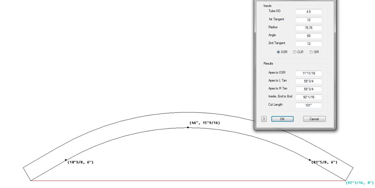
92/4.5
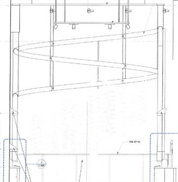
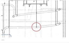
Here are the main drawings with some of my observations and questions.
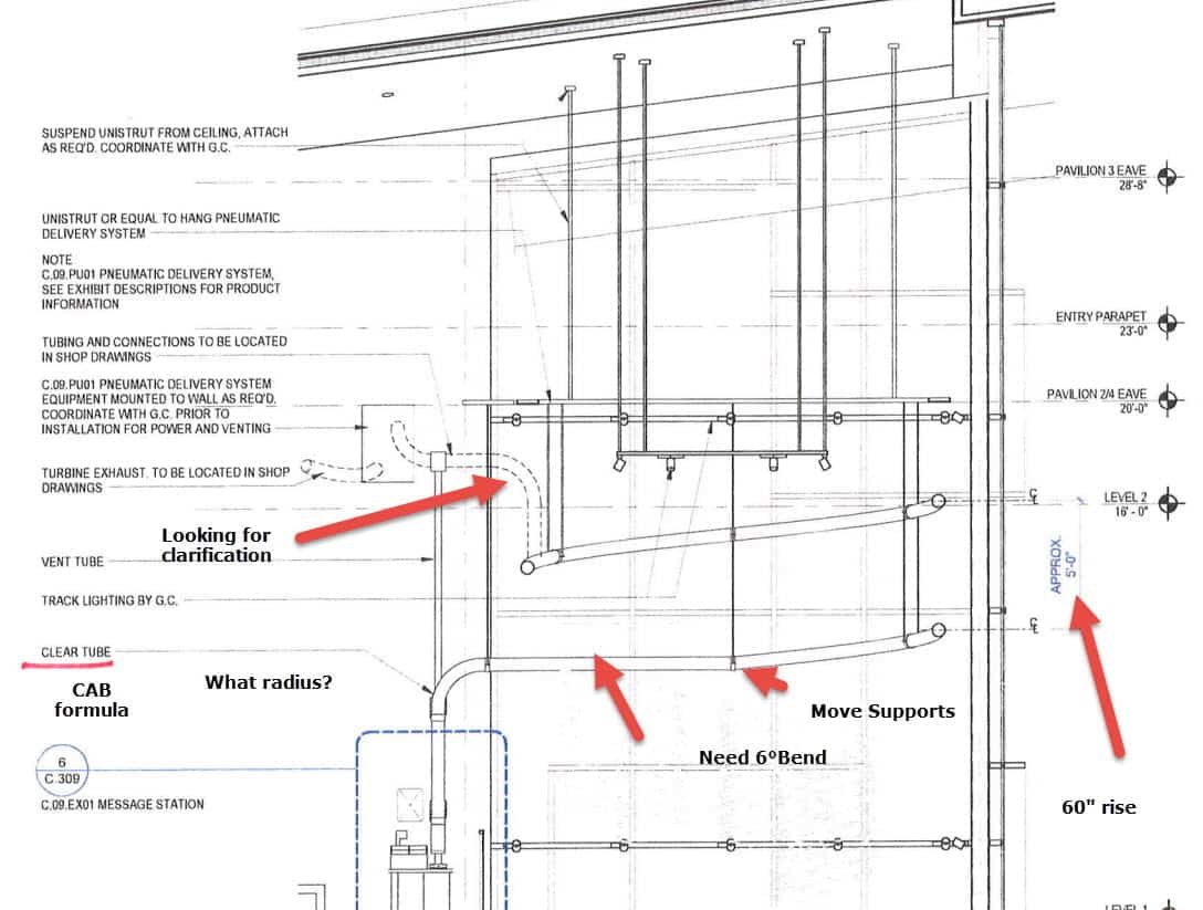
I know that we discussed the dotted line bend, but I still need clarification on the diameter and radius.
I would like to know who is responsible for making sure that the helix lines up to the pneumatic boxes.
Testing of the 24″ Radius input and exit bend.
February 2017
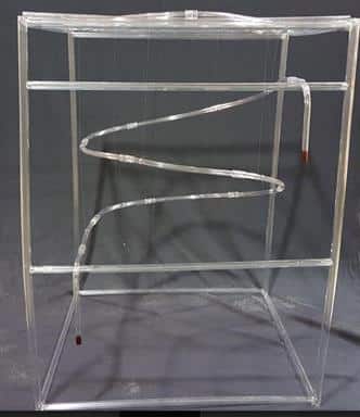
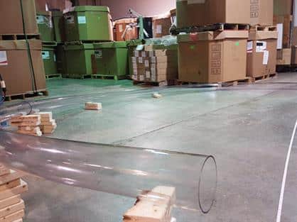
And so it begins!!!! The first two sections.
The first two sections come together. They are in a split coupling with just wood supports for a rise. The rise angle is not important at this time. We just need to get the sections placed together. Altogether we need 10 sections for the 1.5 tiers for this project.
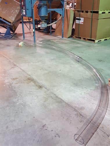
Here we have the third section. Since these are all 60 Deg, we have 180 degrees and half of the circle.
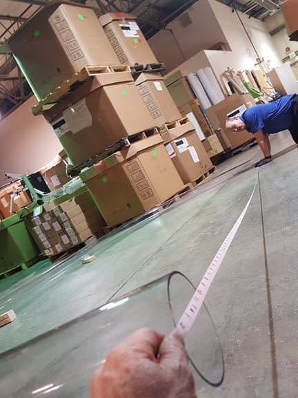
Now, we can test the diameter. The Helix was designed with 12″ tangents and a 76″ Center Line Radius, so we are hoping to get a 16″ diameter. Since we have long tangents, we can modify the entire tangent by simply removing some tangents along the way.
Bingo! Spot on. It’s nice when things work the first time (or so we think). We have a 16″ Center Line.
The Helix is flexible and we’ll see how it winds around.
But first, we want to see if the carrier travels smoothly.
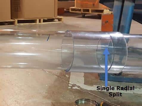
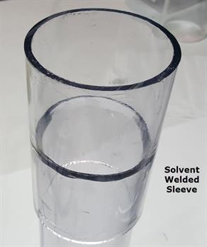
When assembling the helix start out with the slit couplings and then after the helix is complete, replace the slit couplings with un-slit couplings and use a solvent weld.
And the assembly.
Testing the Helix.
When hanging the helix, find the metastable position of each section.
Demonstration of Meta-Staple position for support.
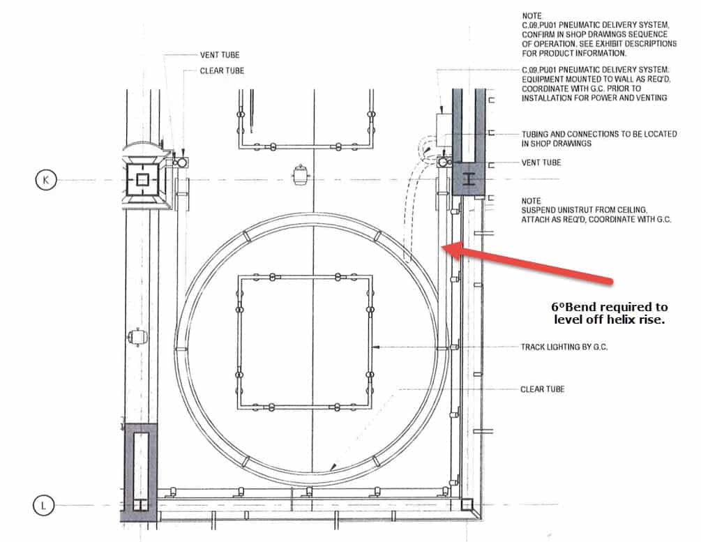
First and last bends have a 6 Degree bend before the tangent. This compensates for the pitch of the bend Arctan(Pitch/Pi*D). With a diameter of 192″ and a pitch of 60″ it comes to approx 5.6 Degrees.
This works out to be 5.8° for a true helix lay angle and it’s 6.4° for the combination of 90° bends at 90-inch radius.
The formula is Arctan(15/(root2 x End to End of bend). The root2 coming from the 45° angle of the tangent from the end to end line.
The neatest way to handle that would be to make one ‘tangent’ longer on the first and last bend and put in a bend of this amount at the end such that it would stick up when the bend was laid flat, but this is possible but impractical. And we would need opposite hand tangents to be modified for the two ends which would then transition to the horizontal tube.
And . . . the test run.
The final part is to make a 2″ saddle on the 24″ Radius bends. The trick is that the saddle comes directly on the arc.
And the precious supervisor.
Suggestions for support ring.